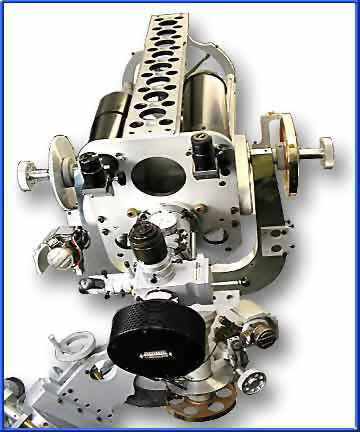
The Completed 10" f/8 RC Scope (Project Started: 10-09-95, Completed: 11-10-01)
One-Piece Solid-Block TITANIUM FORK
cut from a 2" thick slab and hand polished to a mirror-like finish


Although this RC scope (AKA "The Unfinished Scope," because of its extremely long creation time) has been sold ($25,000, and cheap at twice the price), I thought the unique construction methods and features might be of interest to ATMs, etc. No I will not build another one - not ever again! Too much effort! This scope has build-quality and features that even God hasn't conceived (explained in depth below). Otherwise, why build it at all? 5 years in the creation and over 1000 hours of effort. This scope was originally designed and built to have conveniences and features that I have always desired in a personal scope, but could never find at any price.
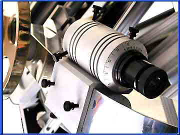
The scope's visual back (pictured above left) has the same large format threads as a 10" or larger Meade SCT (3.25"-16tpi) and fitted with a 2" format (you guessed it) VSI M4 focuser. For show, the focuser totes a Slider 2 with a CCD camera. There are actually four scopes in one: the main 10.25" RC optics, a 3" refractor view finder, a 3" Maksutov guide scope, and a polar alignment scope (close-up picture above) which is conveniently mounted to one of the titanium fork arms which is parallel with the RA axis. I have created a time-lapse picture (directly above) to illustrate [what I consider to be] a super feature, the worm driven altitude adjust mechanism ("Look, no awkward wedge!"). Just loosen the lock-knob and turn the crank (see arrow above), which turns a brass worm and 1/4 section [tangent-type] worm gear. Originally, the altitude adjustment was not going to go all the way up to alt/az (or is that down?), but with all the after-market alt/az computer controlled drive systems on the market, I thought this would give the scope another useful function.
I thought long and hard on the drive system for this special scope. It could have been anything from simple synchronous motors for tracking only, to GO-TO computer control. I decided to go with the classic, super precision synchronous motor control on both axis with variable frequency generator control in RA. With adjustable friction clutches on the 7.5" Byers worm drives in both axis, you can simply slip the scope's clutches and manually move to various celestial objects, if you want, using the 8" diameter brass setting circles. When you let go of the scope, the drives automatically take over for tracking just like most of the commercial scopes on the market. This "tried & true" method saves wear and tear on those precision worm gears because you are not forced to slew your scope to another position by driving your encoder equipped motors, like the current generation of GO-TO SCTs (LX200s, Next Gen, etc.). If you slip the clutches with a GO-TO system, you're "lost in space" until you re-initialize your scope. Of course there are ways around this dilemma by simply attaching your encoders directly to the RA and Dec shafts of your scope (not as hi-res, but adequate for location puposes) instead of attaching the encoders to the armature shafts of its drive motors (I installed the former RA/Dec shaft system on my 30-inch Cassegrain at BFO using large diameter metal spur gears - no sloppy rubber cog pully drives). Precision micro-tracking for astroimaging is achieved by altering the line frequency (from 40 to 80Hz) in RA and activating the synchronous Dec motor for position correction. There is no periodic-error-correction (PEC) because it wasn't even a factor on my priorities list of "must-haves" for this scope. Explaining further, commercial SCTs need PEC because their worms are so inaccurate that PEC is a necessity. Byers made the finest worm drives, period. They are a literal factor of ten better because he used ultra-precision machining equipment that is designed to provide an accuracy of 0.0001" where all the commercial [mediocre] drives are manufactured on machines with accuracies of only 0.001" where 0.003" is the norm. Auto guiding can easily correct for all your other tracking errors, including PEC. Worm excentricities are the least of your concerns compared to low altitude refraction of the Earth's atmosphere, turbulence (seeing), polar alignment errors, mount axis errors, lateral image shift and optical axis misalignments. You will always have to correct for a myriad of undesirable tracking factors, PEC being one of the lesser concerns on a scope with hi-accuracy worms, like this one. As an after thought, I also installed faster, variable speed DC servo motors in both RA and Dec to provide fast and convenient centering of celestial objects in your field of view for visual observing. The full-featured hand paddle has 10 push buttons in all. Just push any of the inner four push buttons for slow synchronous motor control in RA and Dec, or push any of the outer four push buttons for fast DC servo motor control. And two more push buttons for focuser IN/OUT motor control. There are also five [motor speed] control knobs on the hand paddle; a ten-turn control knob (pot) for very fine variable frequency control, two knobs for RA and Dec DC servo motor speed control, and two knobs for IN/OUT focuser motor speed control. Since there is a universal drive train on each axis, with plenty of room for additional drive systems, you can easily upgrade as more sophisticated drive systems become available as an after-market add-on, if you want.
The philosophy behind choosing this classic simple drive system was to follow through with a single-minded concept of precision, not perfection. Synchronous motors are still beyond all others for tracking accuracy. The idea here is functionality, timeless design, and build-quality beyond any other scope. This is not a telescope, it is the epitomy of precision metal art that will be immediately worth many times its purchase price (because I only asked a small fraction of the actual value considering the time and effort I have into this creation) and appreciate in value over the decades. This scope will not wear out and fall apart like all the mass-produced [made in China] commercial scopes of today with their Nylon bearings, thin-wall pot-metal castings, sheet-metal construction and plastic parts.
By the way, if you don't know a lot about optics, the Ritchey-Chretien (RC) optical system (hyperbolic-hyperbolic) was chosen because it is simply the finest optical configuration out of the myriad of possible Cassegrain optical configurations (i.e. Classical, Schmidt, Maksutov, Dall-Kirkham, etc.) This is why all, I repeat all, the large observatory scopes are RC configurations. The stars, observed through this scope, are tight micro-diamonds, always with double diffraction rings, and the backgrounds are absolute velvet black on black. Optically, it doesn't get any better than that. I don't know how you can get 'ideal refractor-quality' imaging with an RCs giant secondary center obstruction, but seeing is believing, and believe me, it works! I've been looking through scopes for over 40 years, every configuration possible and some that were said to be impossible, and there is nothing better than an RC. Even a quality APO refractor pales by comparison.


ABOVE LEFT: The gigantic 6-inch diameter tapered-race roller bearing in the base of the azimuth axis.
ABOVE RIGHT: The dual rows of needle thrust bearings in the upper head of the right ascension (RA) axis, providing additional lateral support to the titanium fork (not shown are the ultra-precision, class 7, dual radial ball bearings supporting the 1.75" diameter, solid stainless steel RA shaft).


![[return]](rulephon.jpg)