


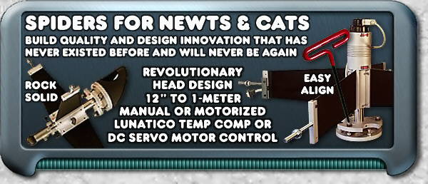
NOTE: Lunatic stepper motor equipped spiders require Lunatic Seletek [Armadillo or Platypus] controller ($300) purchased separately from [Go to] Lunatic Astronomical web site. Since VSI uses Lunatic stepper motors on all their focusers and Zerotators too, click on FOCUSERS link (above left), then AUTOFOCUS link (above right) for further info about Lunatic Astronomical. Also requires CCD camera, computer and appropriate software (i.e. ASCOM, CCDSoft, MaximDL, FocusAide, etc.). Also see Motorized Spider Hubcans for Remote Focus section below.

Floating stainless steel (SS) ball [bearing] & socket adjustable head design (see details below)
Adjustable floating head design provides "center-locked" zero lateral shift
Super simple "3-Allen-screw" head alignment - no springs or 4-screw push-pull mechanisms
NEW 2-Axis Shaft Micro-Collimator provides perfect [Newt] mirror alignment (optional)
Vane/tube threaded rods are rigidly fixed to vane ends - no swivels to cause flexure/misalignments
Reversible vanes and spoke staggering capability increases rigidity (see details below)
Extra long (11") T-handle Allen wrench included for quick & easy head alignment
All stainless steel (SS) and aircraft-grade 6061-T6 aluminum construction
Ultra-thin stainless steel vanes (0.024" to 0.048" depending on spider size)
Tempered & hardened SS vanes - An exclusive VSI rigidizing process w/3x the stiffness of ordinary vanes
Zero shift/flexure push-pull-rotate [solid] stainless steel hub shaft
Double shaft locking quarter-turn metal thumb screws
Motorized remote focusing head assemblies for Cassegrains
DC servo w/hand paddle or Lunatic (temp comp) stepper (requires controller)
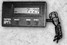
Analog dial indicator or digital read-out available on DC servo motorized model only
Aircraft-grade 6060-T6 aluminum (NAS620 or AN960 aeronautics specs) or better
Military specification 18-8 stainless steel (MS15795, MS27183 or ASTM A693) or better
Secondary head sizes: Newtonian (from 2.14" to 6" minor axis), Cassegrain (3" to 12" sec. dia.)
Custom vane lengths for any tube diameter at no additional cost - Just tell us your tube diameter
Base weight less mirror holder: Approx. 6 lbs. for SH3, 9 lbs. for SH4, add 2 lbs. for motorized models
NOTE: The SH2 should have at least 1 inch of clearance between your primary mirror and the ID of your scope's tube. The SH3 should have at least 2 inches and the SH4 should have at least 3 inches of clearance. This is not a spider mounting requirement. This is to prevent your tube's internal eddy currents and turbulence from interferring with your incoming parallel light path and distorting your images. A 12" mirror should have a minimum 14" ID tube, 18" mirrors should have a minimum 22" ID tube and 30" mirrors should have a minimum 36" ID tube, etc. My 30" Cassegrain at Black Forest Observatory had a 36" tube diameter and it still had problems with tube currents. Paul's rule-of-thumb says that for every foot of primary mirror diameter, you require a minimum of 1 inch of clearance around your primary mirror. - PBVS
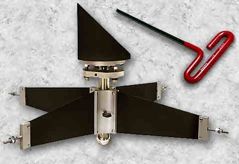
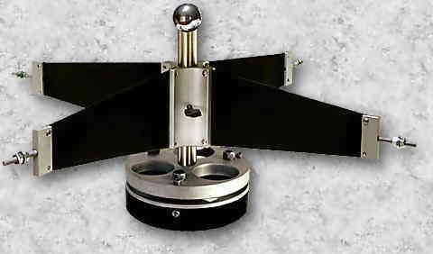
 VSI's SUPER spider assemblies offer a revolutionary head adjustment design.
Until now, all you had to select from were wobbly 3-spring heads or dysfunctional
4-screw push-pull heads. The former never maintained alignment and the latter
was extremely difficult to adjust - tighten/loosen, tighten/loosen, etc.,
etc. With VSI's new ball and socket design, all you have to do is turn any
of the three Allen head bolts clockwise or counter-clockwise, using the included
9" long Allen [red] T-handle wrench (pictured above). No loosen/tighten forever
scenario, and the head stays rock-solid and perfectly centered because the
"floating" ball is always in the center socket.
 VSI's
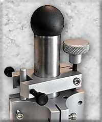
NEW [optional] 2-Axis Shaft
Micro-Collimator for Newts (pictured at right) provides two additional axis
of micro-adjustment above and beyond the omni-directional head adjustment
pictured above left. To our knowledge, this unique collimation device is
exclusive to VSI and has never been offered on any Newt spider assembly in
the past. The Micro-Collimator adjusts the spider rotationally and up and
down with the simple turn of thumb screws. The large aluminum knob on the
right push-pulls the shaft and the two black thumb screws on the left rotate
the shaft clockwise and counterclock-wise. In addition to the 3-point
collimatable head, this simple and effective device offers critical Newtonian
secondary mirror alignment that has never been possible before now.
The manually operated spider hub has a solid stainless steel (SS) shaft that is loaded to maintain a zero-tolerance in any position and has double [quarter-turn] metal thumb locks (non-motorized only). It is simple and functional offering push-pull-rotate head positioning for Newt diagonals and push-pull operation for Cassegrain secondary optics. With Newts, once you have your diagonal in the mechanical [shaft] position you want, simply adjust the three SS Allen head bolts to fine tune your alignment. With Cassegrains, simply align the head using the three SS Allen head bolts and push-pull to set your back focus. Cassegrain SS hub shafts offer 3 inches of travel for the SH3, equating to 18" of adjustable back focus, and 5 inches of travel for the SH4, equating to 30" of adjustable back focus. No more flexure-ridden drawtubes when changing visual back configurations. Just loosen the double thumb screws and push-pull to set your desired back focus. Your head alignment is always perfect, no matter where you position it, because the hub/shaft always maintains a zero-tolerance.
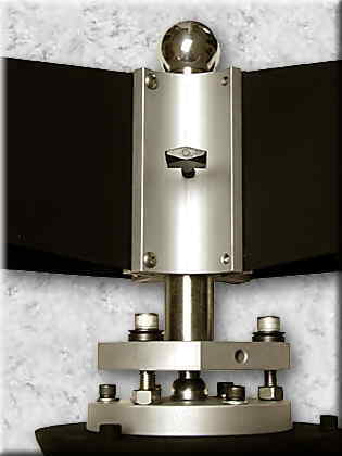
 Above is a picture of
the vane hub, SS shaft and head assembly. Note the SS ball centered between
the two disks. Each side of the "floating" ball (spherical to 25/millionths
of an inch) is suspended in sockets allowing the lower disk to be rotated,
using the three Allen bolts, while maintaining perfect center alignment.
Of special note, look at the two-piece washers under the Allen bolts above.
Those are spherical dish & seat washer sets, imported from Germany. They
are machine trued and case hardened, always providing perfect bolt alignment,
even when the lower disk is misaligned with the upper disk. Also note the
SS nuts at the end of the Allen bolts. Those three nuts can be tightened
when alignment is achieved. Notice that I said, "can be." Locking the head
is really not necessary, unless you are taking your scope to a star party,
etc. Even then, extreme vibration could not dislodge your alignment even
without these nuts locked in place. These three nuts are simply there because
they can be, not because they need to be. And if you do happen to use them
to lock the head, they work with the pull of the bolts, not against them,
so tightening them changes nothing, alignment wise.
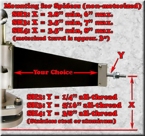
At right is a close-up picture of the the end of each vane, where it attaches to your telescope's tube assembly. Instead of using single-point swivel bolts, like other spider vanes, VSI uses a full-length slotted bar, which is bolted at both ends of the vane to prevent this swivel motion. This rigid method of vane-to-tube mounting provides a more solid spider installation compared to single, swivel-type, split-bolt designs. VSI's NEWEST feature is our reversible vanes and staggered spoke capability (see below for details). Each vane is also hand tempered & hardened. An exclusive VSI rigidizing process that offers 3 times the stiffness of ordinary vanes.


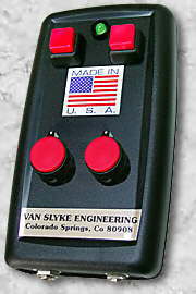
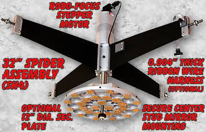
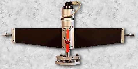
Pictured at left are four motorized [what I call] hubcan assemblies, shown without vanes or Cassegrain mirror holders mounted to their heads. These "hubcans" are not real cans, like soup, etc. They simply looked like cans, thus the name "hubcans" like hubcaps, etc. These hubcans are 1/4"-wall aircraft-grade 6061-T6 extruded aluminum with machined ribs and 1/4" plate aluminum [top and bottom] caps. All VSI products are exclusively constructed from two metals (including hardware), the above grade of aluminum and stainless steel. All motorized hubcan configurations provide 3" of travel (18" back focus range), discussed in more depth below. These hubcans are available in four different motorized configurations pictured at left. From left to right: Lunatic stepper motor, Robo-Focus stepper motor, DC servo motor with analog readout and DC servo motor with digital readout. Both stepper motor models can be computer controlled and internet accessable. Both DC servo motor models come with manual hand paddle (pictured above) and can not be computer interfaced.
 Because of VSI's exclusive
OFF-axis helical screw [non-rotational] design, there is literally zero star
wobble when focusing. Many other designs use a complicated ON-axis helical
design to move their spider heads in and out. Our simple zero-tolerance design
guarantees zero "everything" when focusing. No wobble, no flexure, no backlash,
no lateral anything. Just perfect linear in-out movement. Our motorized hubcans
offer a full 3 to 5" of travel, depending on model. Since primary/secondary
separation usually equates to a 6 to 1 focus ratio (depending on your focal
length), you receive 18" to 30" of back focus range behind your visual back
with the push of a button!
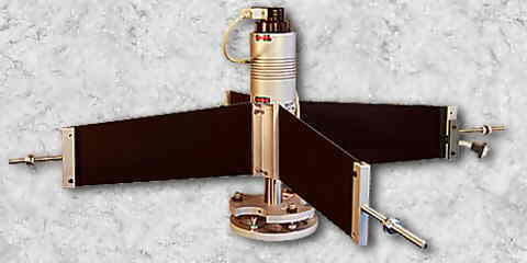
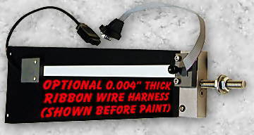
Motorized hubcans [electrically] connect their motors and digital read-outs to the outside world via an optionally installed multi-conductor flat cable strip attached to the side of one spider vane (shown at right & below). These special ultra-thin cable strips are only 0.004" thick. Yah, that's four/thousandths of an inch! Since the stainless steel vanes are 0.024" thick (0.060" thick for SH4s), the cable strip is microscopically thinner than the vanes themselves. That factor renders the cable strip thickness negligible to the "spider spike gods."
 A motorized secondary
spider is not just a luxury for your Cassegrain. Even if you already have
a primary focuser behind your visual back, you need a motorized spider for
many reasons. Mainly, to change your existing back focus for your various
equipment configurations. Why use awkward, flexure-ridden drawtubes, when
you can simply push a button to change your back focus to exactly where you
want it. Then simply use your [now] secondary focuser to fine tune things.
This mode of operation was my favorite during the days of Black Forest Observatory and the 30-inch Cassegrain (see Installations link, bottom of the page for more info). To change from visual to imaging mode, I had to move my back focus point outward by about a foot or more. Since the 30-inch was equipped with a motorized secondary and a standard visual back focuser, all I had to do was push a button to move the secondary closer to the primary and increase my back focus point. What a luxury! And very functional, too.
Or, you can use your motorized spider to completely eliminate the profile consumed by your "behind the visual back" conventional focuser. I shouldn't say that, since VSI offers the largest selection of primary and secondary focusers on Planet Earth. Seriously, a motorized spider can make your focusing efforts much easier and less frustrating.
 Many zealots think that
the distance between primary and secondary Cassegrain optics should be fixed
at a point that is mathematically and optically correct. This is perfectionist
rhetoric. Sure, there is an ideal [Cassegrain] separation between the primary
and secondary, but this can vary by many inches, and you or your camera will
not know or see the difference. Commercial Schmidts and Maksutovs change
this separation by moving their primary back and forth in relation to their
secondary optics. It works great. To continue briefly from the above paragraph,
I created a motorized secondary for my 30-inch Dall-Kirkham Cassegrain that
had a 6" range of travel, allowing me a whopping 36" of adjustable back focus
range. Again, it worked great.
My 10" Ritchey-Chretien changed it's back focus by turning a knob on the sky side of the secondary hub (more about these scopes at the USER INSTALLATIONS link, bottom of the page). I noticed no aberrations, spherical or otherwise, when the separation was extended all the way in or out.
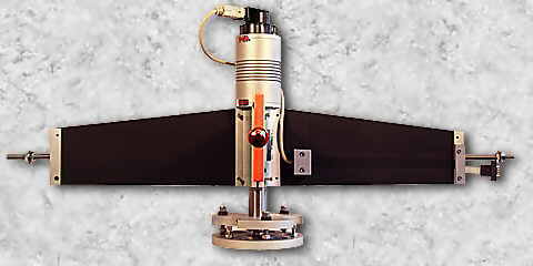
Instead of a conventional vane with a symmetrical taper, all vanes are straight cut on one side and angle cut on the other, as illustrated above. Reversible vanes offer an increased spacing range selection between your secondary and primary mirror. Vanes are offset cut to allow for one inch of spacing adjustment simply by reversing the four vanes in the hub slots. By request, a steeper vane taper is available offering two inches of reversible spacing adjustment. This increased spacing capability is in addition to the three inches of [stainless steel] rod travel that is built into the head assembly. Why would I offer this redundant capability? Because I can.
When you receive your spider assembly, simply install the vanes in the hub slots with the straight edges toward your primary mirror, which is the conventional installation method (as shown in the left picture above) or with the straight edges toward the sky (as shown in the right picture above). Of course, this reverse capability is for installations where you are retrofitting or upgrading your scope to a VSI spider assembly and don't want to drill additional holes in your tube, etc. Also, many upgrade installations switch from a lesser spider assembly, that is shorter in length and not as substantial as a VSI spider, so an extra inch or so of adjustable spacing range can make the difference between drilling new holes in your tube, or not.
The staggered spoke capablity is simply another [of the many] integral options that extends the versatility of a VSI spider. However, this staggered spoke capability does need some further explanation because it is another revolutionary design feature that has never been offered before, by anyone. The concept of staggering the vanes was actually first introduced in a paper by Edgar Everhart and Joe Kantorski called "Diffraction Effects Produced by Obstructions in Reflecting Telescopes of Modest Size." It was published in the Astronomical Journal in 1959 and reprinted in Sky & Telescope in 1960.
Coincidentally, I knew Edgar Everhart personally. He and his wife lived in Colorado Springs before his passing. The late Dr. Everhart came out to my observatory on many occasions. He even spoke at meetings of my [now disbanded] Rocky Mountain Astrophysical Group (RMAG) from time to time. Edgar was also the brother in-law of Clyde Tombaugh, the discoverer of Pluto.
Their proposal was to use eight staggered wires to mount the central mirror hub. Beta testing by others indicated that the wire supported spider showed no diffraction spikes around bright stars. Was the diffracted light dispersed across your field like curved arm spiders (see "Spider Vanes and Star Spikes" below), or did it magically disappear? Obviously, the diffracted light has to be in your field somewhere. We scientific types don't believe in magic. Of course, the wire spider is an interesting topic for an academic discussion, if you have nothing better to do. It is not practical or mechanically functional in the real world. It would be terribly tedious and complex to actually install a wire spider. The central hub would need to be substantially longer to properly stabilize the assembly. And the eight wires would require the exact same tension on each wire. It could be done, but who would want to do it? Certainly not me. But using the same principle to stagger a couple of vanes was beyond easy. All you needed to do was reverse the opposing vanes to achieve an increase in structural stability.
If you look closely at either of the pictures above, you will see that the center bolt on the end of the vane directly facing you (shown in red) is offset compared to the two opposing vanes. The bolt in the left view is above the other two and the one in the right view is below. The perpendicular vanes are reversed from the other two (one up, one down, one up, one down) like a spoked wheel on a motorcycle. They are opposed by 90 degrees in pairs providing two different non-radial centers. This type of lateral tensioning can add much stability and extra rigidity to a spider assembly, compared to vanes installed around a flat or radial circumference. Best of all, the above options are integral to the design. To implement them is yours to consider. Your choice - reverse or stagger? - PBVS


Note the spider vane patterns created from various vane configs above. The 2-vane spider (left above) creates two optical spikes. The 3-vane spider (center above) will actually create 6 spikes. And, obvioulsy, the 4-vane spider (right above) creates 4 diffraction spikes. All of the various vane configs create their respective and distinct optical spike patterns, but only one is structurally stable and mechanically rigid in all rotational and gravitational positions.
I should briefly mention the single vane spider, which will produce a diffraction pattern similar to a 2-vane spider. 1-vane spiders are not structurally practical because the single vane needs to be very thick to keep the secondary holder stable, producing 2 diffraction spikes, one is usually larger than the other. And a 2-vane spider is not that practical either because the vanes have to be fairly thick to prevent perpendicular twisting caused by a lack of lateral support that two more vanes would provide. Obviously, a 3-vane spider is much more structurally stable than a 2-vane, but six diffraction spikes may not be a desireable optical effect. And a 3-vane spider is not as structurally stable as a 4-vane spider because the tensioning can't be evenly distributed. A 4-vane spider can be tensioned/stabilized to a higher degree because the mechanical stretching forces are directly opposite each other, and opposed by 90 degrees.
Although I don't consider curved vanes or arm supports mechanically practical, we can briefly discuss the reasoning behind my exclusive support for the (spike producing) 4-vane spider. You don't see any spikes around stars with curved vanes because the diffracted light is dispersed across the brighter part of your image. However, it is still there. You just can't readily see the stellar spikes. A curved arm support always requires thicker vanes because they can't be tensioned properly like directly opposed vane arm assemblies. I suppose the curved vane would be practical for double star observation and other stellar-point analysis because you don't have to contend with spikes to disrupt your astrometric measurements. However, if you are observing non-stellar objects, such as nebulae or galaxies, your image will lose significant contrast because the diffracted light would be concentrated around the brightest areas in your field of view.
Therefore, in my humble opinion, the only practical, functional and mechanically stable (not to mention simple) spider assembly is the 4-vane spider, hands down over any other configuration. I hope I have provided a simple explanation regarding the different types of secondary support arms and their mechanical advantages and disadvantages. The above is the reason I exclusively produce 4-vane spiders. - PBVS

 The ultra build-quality of VSI spiders has never existed before and will
probably never exist after VSI is gone. VSI spiders are not the "Novak" spiders
of yesteryear. If you are interested, you can see display ads in old S&T
magazines for Novak spider assemblies. They were acceptable spiders for the
time, built from a section of steel water pipe, with a length of all-thread
through the center, and two nuts on either end. The clearance between the
inner wall of the pipe and the all-thread was usually enough to insert your
little finger. If memory serves, Novak spiders had straight (not tapered)
vanes that were made from some kind of strapping that was permanently brazed
to this pipe section. A length of split all-thread [that swiveled] was pinned
through the vane ends. I could never understand why there were swivels on
the end of the spider vanes? I still don't know why swivels were used back
then, and are still used today on many spiders. Is it simply convention?
These pivot points cause your secondary mirror to be out of alignment with
your primary more often than not. Novak's collimatable heads were the 4-screw
dysfunctional type, that I mention above, where you had to loosen, then tighten
the opposite screw continuously to collimate the mirror head. I remember
the frustration when I tried to align my secondary mirror many years ago.
Yes, I too had Novak spiders long ago.
My intention is not to denigrate the Novak spiders. They were adequate, inexpensive and functional for the time. I am simply trying to make a point about today's VSI spiders. Understand that VSI does not build spider assemblies, or anything, to minimum standards. - PBVS